Just an up front note:
This is purely a Nikon based project as it uses Nikon’s own IR remote. I have some ideas how this could be modified or a new system could be built that would work for pretty well any camera with a remote shutter connection.
A bit of a background about how this came about. I was talking with a mate about these amazing close up photos of sharks he’d been getting and the way in which he was taking them. Basically he has his underwater camera (Nikon DSLR in an Ikelite housing) and strobe mounted on the end of a pole which he holds over the side of a boat and takes photos of sharks, or other things, that show enough interest to come in close. It seems as though this type of thing is not too uncommon and there are many others out there capturing photos this way with an array of methods including using cables, levers, rope or string, etc. to control the camera and take the photos. From what I’ve seen they all work but may give little or limited control over the focus and timing of the pictures. This got me thinking that there had to be a better way, and there had to be a way to make something that would give the same control as a normal camera remote. I remembered I used to have a Nikon ML-3 infrared remote which I used for long exposures and lightning photos, and with a bit of convincing I persuaded him that we could modify one of those and add a few extra bits to do the job and with a bit of trial and error we worked out a way to do it.
Below is the first build of our PoleCam infrared remote. It is a bit rough around the edges, and I’ve already thought of plenty of ways to make it better. But hey it works.
The Parts List
- Nikon ML-3 Compact Modulite remote
- 3m Toslink Cable
- Casting resin
- 3mm Perspex
- Weather resistant double sided tape
- 3/16 x 1/2 inch Stainless steel screws and wing nuts
- Araldite
- Liquid electrical tape
- Silicon Marine sealant
- Small plastic vials
- Black electrical tape
- Screwdriver, soldering iron, drills and hacksaw


The bare essentials
First things first, disassemble the ML-3 main unit. There is no way we can fit both that and the camera in the camera housing.


There are two circuit boards inside one with the IR receiver and the other with the power/channel switch, LED and socket. There is also a lens in the housing of the unit that needs to be kept.
The space in the camera housing is quite tight but there is enough room in the lower right where this could fit and provide a clear view for the IR receiver to the outside world.
To minimise space we cut down the switch leaving a very small stub. We left the switch set to channel one. The leads on the LED were also shortened and we trimmed back any long pins under the circuit board to minimise any scratching in the housing.
There are three wires going to the IR receiver board, these needed to be lengthened to enable the repositioning of the two boards. These wires were replaced and redirected to come out the back of the IR board instead of underneath. This board was then soldiered, at right angles, to the side of the switch on main board (see below). The electronics were then coated with liquid electrical tape

For protection the entire unit was then encased in marine silicon. We also glued the lens from the original remote unit onto the front of the metal shielding (more on that later).

Below is the finished modification as it sits in the camera housing. We haven’t had to mount it into position, the camera holds it in place pretty nicely.

Good communication is the key
So after having sorted the receiver part now we need to get the signal down to it. Given that the remote signal is using light, albeit Infrared light, we figured that we could transmit it down an optical cable. From our initial trial and error process we knew that we could transmit the signal through a short 1.2m Toslink cable. This was too short for what was needed so so we upgraded that to a 3m cable. Testing indicated that signal still reached the receiver but there was some loss, attaching the lens to the receiver unit fixed it.
The Toslink cable is not water proof, so we encased the ends of the cable in casting resin using the small vials as moulds and coated the back of the cable plug in silicone to seal it.

Making the connection
OK so we have the remote receiver, the cable and the remote control sorted. It all needs to be connected. Two mounting systems were created using the 3mm Perspex. At the camera end we fashioned a small mounting plate about 20mm wide and 60mm long. We drilled a hole in the centre to mount the end of the cable and two holes either side to accommodate the mounting bolts. The cable end is held in place with marine silicone.

We initially tried Velcro to fix the mounting plate to the housing, but this proved unreliable. So we made a more solid fix using stainless steel bolts. These were set into two small Perspex tabs using Araldite. Then using the mounting plate as a guide we stuck these mounting bolts to the side of the camera housing with double sided tape. We then used the stainless steel wing nuts to mount the cable to the side of the camera housing. The mounting bolts aren’t in a position that causes any interference to normal operation so they stay on the housing when the remote is not in use.


The mounting at the remote end of the cable was similarly fashioned out of 3mm Perspex. This time we fashioned a 20mm wide strip into a U shape the same width as the remote. We then drilled a hole for the cable in the flat at the end so that it would align with the transmitter LED in the remote. The cable is held in place using the silicone.

The mount was fixed to the remote using the double sided tape. The end was then wrapped in black electrical tape to minimise light interference.

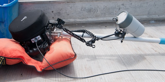
The pole and mounting bracket
The pole and bracket are composed of an aluminium telescopic pool cleaner pole and a custom made aluminium bracket. The bracket is a hinged adjustable aluminium bracket that Justin had custom made by a local fabrication business. The bracket mounts onto the bottom of the Ikelite housing and bolts onto the end of the pole.


In use the remote is sealed in a plastic bag and attached to the Pole. The setup provides all of the controls available on the remote including focus and single or continuous shooting. One downside of the remote unit is that it draws power once the remote receiver is turned on and connect to the camera, irrespective of whether the camera is turned on or not.

Leave a comment